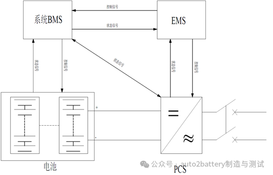
A complete energy storage system BMS should include a plug-in BMS, a battery cluster BMS, and a system BMS. Especially for large-scale energy storage systems, a three-level BMS can avoid voltage imbalance and resulting overcharge or overdischarge to the greatest extent.
According to the different levels of PCS, power frequency boost PCS can be divided into single-stage and double-stage. Among them, single-stage PCS is divided into two-level, three-level and multi-level according to the output level. The more levels, the higher the output power quality.
The overall architecture of EMS can be divided into support platform and application software. The support platform mainly includes measurement terminals, transmission channels, computers, databases, etc. The application software includes data collection and monitoring, energy management, and network analysis (the energy storage system control structure is shown in Figure 2).
2. Classification of common energy storage system inverters
Currently common energy storage inverters can be divided into centralized, distributed, and string types.
2.1) Centralized energy storage inverter solution (see Figure 3)
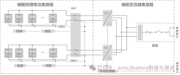
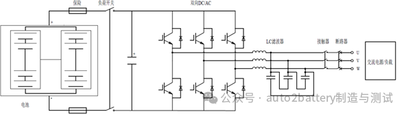
The centralized energy storage inverter solution is mainly used in large-scale ground power stations. The topology diagram from right to left is: high-voltage switch cabinet-transformer-2* energy storage converter-2* bus cabinet-battery cluster. After converging from the DC side, the inverter is centralized. The system topology adopts DC-AC one-level full-bridge inverter.
2.2) Distributed inverter solution (see Figure 4)
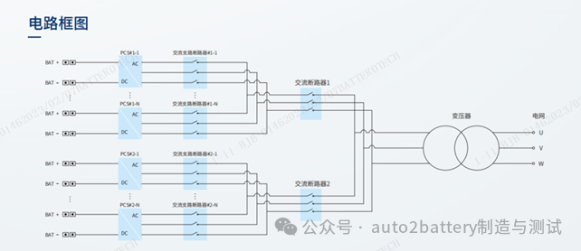
Figure 4 shows the topology diagram of the distributed energy storage inverter: transformer-string inverter-16*battery cluster (maximum). The converging cabinet is omitted, and the AC side is converging after the DC side inversion is completed. Adopt DC-AC one-level conversion.
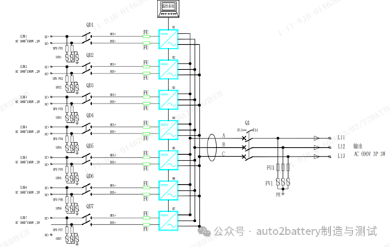
Figure 5 is the topology diagram of the distributed inverter. The main difference from Figure 4 is the design of the breakpoint. Figure 5 is the DC side isolation switch + fuse solution, and Figure 4 is the AC side circuit breaker solution. The disadvantage in Figure 5 is that the inverter fails and the upper-level switch needs to be disconnected. The advantage is that the DC side has short-circuit protection. The solution in Figure 4 can disconnect the AC side and maintain a single module. The AC side switch is outside the PCS module and the wiring is complicated.
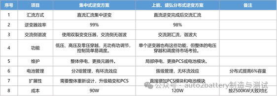
Comparison between centralized and distributed inverters
2.3) String inverter solution (see Figure 6)
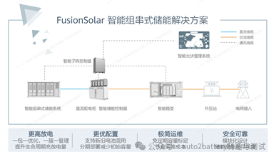
Not only does it manage one cluster per cluster, it also installs an optimizer on the battery PACK to implement energy management down to the battery module level. The available capacity will increase by about 6%. And supports the mixed use of new and old batteries.
Note: All the above content comes from the Internet, learning makes people happy!

عنوان : Room 2303-3, No. 466 Xinglinwan Road, Jimei District, Xiamen City
هاتف : +86 18059873669
بريد الالكتروني : Kevin@swt-power.com
Skype : live:.cid.2616da0477d4d425